Plane Wave |
The plane wave source algorithm generates a plane wave within a specified closed rectilinear volume. A plane wave is useful when computing the electromagnetic responses from a source that exists at a great distance from the object being modeled. The plane wave is generated by computing electric and magnetic current density values on the equivalent surface of the rectilinear volume. These are then injected into the equivalent surface electric and magnetic fields in the proper manner, and with the proper retardation time, to generate a plane wave within the surface boundary. The plane wave is confined to the equivalent surface volume.
Click Plane Wave
 within the Excitation panel under either the MHARNESS or EMA3D tab in the Ribbon.
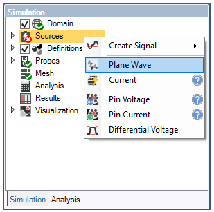
Alternatively, right click Sources in the Simulation Tree and select
 Plane Wave.
Green, red, and blue curved arrows will appear in the model window that can be used to adjust the propagation and polarization angles.
The straight, yellow arrow is the resultant electric field polarization vector, the straight, black arrow is the plane wave propagation vector, and the straight, blue arrow is the magnetic field vector. To see the vector labels, change Show Names to True in the Properties Panel.
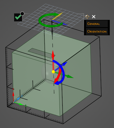
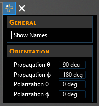
Adjust the properties of the plane wave propagation and polarization by dragging the curved red, blue, and green arrows. Alternatively, enter the propagation and polarization angles in the Properties panel. The adjustable properties and their definitions are provided in the table at the bottom of this page.
The plane wave source will be added to the Simulation Tree under the Sources node as Plane Wave.
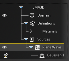
A Gaussian signal is automatically applied to the plane wave, but it can be edited or deleted and replaced by a different signal. Instructions on adjusting signals can be found here.
Click OK
 to complete the plane wave setup.
Entry | Meaning |
|---|---|
Show Names | Show the vector labels |
Propagation φ | The angle of the plane wave propagation vector with the X axis |
Propagation θ | The angle of the plane wave propagation vector with the Z axis |
Polarization φ | The angle of the Electric field vector with the X axis |
Polarization θ | The angle of the Electric field vector with the Z axis |
Other Resources
EMA3D - © 2025 EMA, Inc. Unauthorized use, distribution, or duplication is prohibited.